Braun Corporation FMVSS No. 403 Quick Reference Installation Sheet 32553 Rev. A
JKA
Thresho
ld
Sen
sor Mat
U
N
F
O
L
D
FO
L
D
D
O
W
N
U
P
4
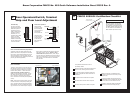
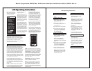
Floor Level and Inner Roll Stop Adjustments
Achieving proper floor level positioning of the
platform and inner roll stop requires a combina-
tion of Floor Level switch adjustment and inner
roll stop adjustment. Both are factory set but
must be inspected during installation procedures
(will vary per vehicle application).
Ensure the lift is positioned and secured as speci-
fied above (panels 1 and 2). Adjust the Floor
Level switch first (detailed below). Then, adjust
the inner roll stop as detailed in the service manual
(adjust only if necessary). The inner roll stop must
rest properly on the vehicle floor for wheelchair
entry and exit.
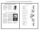
Floor Level Switch
The Floor Level switch stops upward travel of
the platform during the Up function (activated
by the torque tube-mounted Floor Level cam).
Position the lift platform 1" above floor level
using the manual operation system (de-
tailed on opposite side of this sheet). Loosen
the clamp securing the torque tube-mounted
Floor Level cam. Rotate the cam until the
Floor Level switch is activated (cam depresses
switch).
Note: Check the floor level position of the plat-
form and the inner roll stop after powering the
pump. Hydraulic pressure may affect platform
height slightly. Fine tuning adjustment (tweak-
ing) of the Floor Level switch may be required.
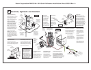
Door Operators/Switch, Terminal
Strip and Floor Level Adjustment
Floor Level Switch
Floor Level Cam
Tor qu eTu be
Cam depressing switch.
Power Door Operators
Figure O
Black
Jumper
12
3 4
5
67
8
9
10
Terminal Strip
The pump-mounted
terminal strip provides
additional inputs and
outputs that can be
used for optional door
operators, beepers,
interlocks, etc. - as
well as the door safety
switch. The black
jumper wire must be
installed in terminals 6
and 9 to supply power
to the circuit board.
C_SW
1
O_RL
2
N/C
3
IN_LK
4
12_V
5
PWR
6
GND
7
F_LV
8
O_SW
9
C_RL
10
To Door Openers
“Close” Trigger
To Door Openers
“Open” Trigger
Door Cutout
Orange
Red
Door Cutout
Black
Blue
Install optional
power door oper-
ators as detailed
in the instructions
supplied with
door operator kit.
Route the wires
to the pump mod-
ule and connect
to the terminal
strip as shown in
Figure P.
Figure P
5
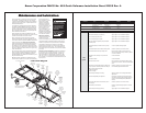
FMVSS 403/404 Certification Checklist
Dual
Outer Barrier
Threshold
Area
Platform
Lighting
Visual andAudible
Threshold Warning
Platform
Inner
Roll Stop
DOT — Public Use Lift
Public use vehicle manufacturers
are responsible for complying with
the lift lighting requirements in Fed-
eral Motor Vehicle Safety Standard
No. 404, Platform Lift Installation in
Motor Vehicles (49 CFR 571.404).
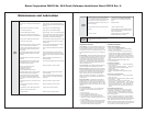
Vehicle movement is prevented unless the lift
door is closed, ensuring the lift is stowed.
Lift operation shall be prevented unless the
vehicle is stopped and vehicle movement is
prevented.
The platform will not fold/stow if occupied.
The outer barrier will not raise if occupied.
The inner roll stop will not raise if occupied.
The operations listed below must be
functionally verified.
Platform movement is prohibited beyond
the position where the inner roll stop is fully
deployed (up).
A visual and audible warning will activate if
the threshold area is occupied when the plat-
form is at least one inch below floor level.
Lift platform movement shall be interrupted
unless the outer barrier is deployed (up).


