


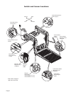
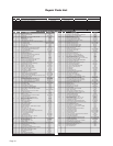
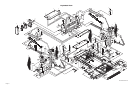


Page 12
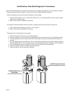
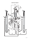
Pump Module Parts List
* Apply red #271 Thread Locker Loctite
®
WRWKHIRXUKH[EROWVLWHPVDQGLIDEOXHQ\ORQSDWFKLVQRWSUHVHQWRQ
WKHEROWVZKHQUHWURÀWWLQJDQ0SXPSDVVHPEO\/RFWLWH
®
is available from The Braun Corporation under part
number 11522.
t Indicates items available for replacement part purposes only. These items are not included with replacement pump
modules.
Item Qty. Description NVL917IB NVL917FIB
1 Pump Module (complete), 12 Volt 985-A3516RNA 985-A3516FNA
1 1 Plate, Backing / Mounting 985-2501RN 985-2501FN
2 1 Cover, Pump, 2-Piece - Back
(915-0513RNA or 915-0513FNA Includes Items 2 and 18 - 24)
915-0513RN 915-0513FN
3 1 Cover, Pump - 2-Piece - Top / Front
(915-0519RNA or 915-0519FNA Includes Items 3 and 38 - 50) 915-0519RN 915-0519FN
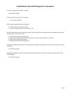
Item Qty. Description Part No.
4 1 Pump Assembly (M268-0112) 12V-120G - Duel Relief (Includes Items 5 & 6) 30915-12V
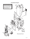
5 1 Power Cable, Up Solenoid to Motor 29049
6 1 Solenoid, Up - 4-Post - Prestolite 28308
7 1 Diode Assembly, Up Solenoid 73906A
8 1 Fitting, Male 7/16-20 O-Ring to Male 7/16-20 JIC 37° 24504
9 1 Elbow, Female Swivel 7/16-20 JIC 37° to (2) Male 7/16-20 JIC 37° 26579
10 1 Control, Hand Pendant Assembly - Standard 32365A
11 1 Strain Relief - Liquid Tight 30753
12 1 Control Board Assembly 100159-001
13 8 Standoff, Snap-In (2 shown) 31011
14 1 Switch, Push Button 31753
15 1 Diode, Green LED, Panel Mount 29545
16 1 Stud, Power Feed 26084
17 1 Rubber Boot, Red tSee note below 82046
18 1 Recepticle, Clip On 28803
19 1 Lens, Threshold Warning - Red 30704
20 1 Decal, Warning / Pressure Relief Valve (Not shown - see Decal Section) 22249
21 1 Spacer, Lens - NHTSA 31386
22 1 Metal Ring Base - Lamp 30971
23 1 Socket, Lamp 30703
6FUHZ[µ3DQ+HDG3KLOOLSV7KUHDG&XW
25 1 Bulb, Light 19841
26 1 Switch, Toggle 12185
27 1 Decal, Lift Power - On/Off (Not shown - see Decal Section) 21494
28 2 Washer, 5/16” Flat 10063
%ROW[µ1\ORFN+H[6HHQRWHEHORZ
%ROW[µ1\ORFN+H[6HHQRWHEHORZ
31 1 Cable, Ground 22166A
:DVKHUµ([WHUQDO7RRWK
33 1 Beeper, Continuous 30487
34 1 Wire Assembly, Lift Interlock Connection 31797A
35 1 Wire Assembly, Lift Stowed Connection 31798A
36 1 Pump Handle with Grip 17206A
37 1 Clamp, Hose - Solenoid Mounting 29663
38 1 Clip, Pump Handle - Bottom 915-5518
39 1 Stud, Wing Head - 1/4 Turn 28804
40 1 Retainer, Push On 28805
41 1 Plug, Window - Clear 30443
42 1 Clip, Pump Handle - Top 915-5517
:DVKHU1\ORQµ,'[µ2'[µ
44 3 Rivet, Pop, SD43BS - 1/8” - .13”/.19” 12954
45 1 Decal, Removal / Installation Pump Handle (Not shown - see Decal Section) 29052
46 1 Decal, Manual Instructions - Public (Not shown - see Decal Section) 31412
47 1 Decal, Removal / Installaton - Pump Cover (Not shown - see Decal Section) 29051
48 1 Decal, Warning - Control Board Damage - ESD (Not shown - see Decal Section) 30787
49 1 Decal, Instructions and Warning, Hydraulic Pressure Switch (Not shown - see Decal Section) 27154
50 1 Decal, Dual Relief Adjustment (Not shown - see Decal Section) 32201
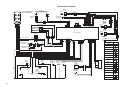
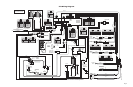
51 1 Cable, Pump Module Power Hookup (Not shown - see Wiring Diagram) 26082A-4
52 1 Harness, Power (Not shown - see Wiring Diagram) 985-A2530NA
53 1 Harness, Interlock / Lighting (Not shown - see Wiring Diagram) 985-0531NA
54 1 Harness, Up / Down Solenoid (Not shown - see Wiring Diagram) 985-2533NA
+DUQHVV([WHQVLRQ7KUHVKROG6ZLWFK1RWVKRZQVHH:LULQJ'LDJUDP $1$
56 1 Harness, Jumper (Not shown - see Wiring Diagram) 985-2541NA
Part Numbers of Items Identical on all Lift Models
Part Numbers of Items Dedicated per Lift Model