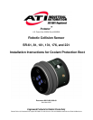
Protector Installation & Operation Manual
Document #9610-60-1008-04
Pinnacle Park
•
1031 Goodworth Drive
•
Apex, NC 27539
•
Tel: 919.772.0115
•
Fax: 919.772.8259
•
www.ati-ia.com
•
Email: info@ati-ia.com
9
2. Design/Procurement of Interface Plates
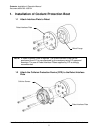
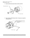
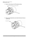
This sealing system utilizes a bellows style boot attached to the cover and stem side
interface plate and a molded wire channel gasket. In order to insure proper sealing the
following items are necessary:
1) The unit must have been purchased from the factory with the coolant sealant boot.
(This is necessary since the cover must contain the groove for the garter spring and be
sealed to the body.)
2) Purchase Custom collision sensor interface plates from ATI. Provide the robot and
tooling interface patterns to ATI and we will design and manufacture custom
interface plates for your application.
or
Purchase blank collision sensor interface plates and modify them as follows:
Tooling to Collision Sensor Stem Interface Plate
a) The tooling mounting holes in the collision sensor stem to tooling interface
plate must be surrounded with o-rings installed in properly sized counterbores.
Robot to Collision Sensor Body Interface Plate
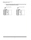
a) The robot mounting holes and dowel hole(s) in the collision sensor body to
robot interface plate must be oriented so that they do not cross the molded wire
channel gasket.
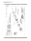
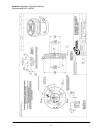
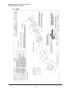
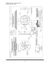
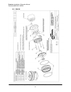
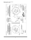
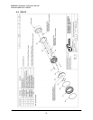
Note: See drawings in section 3 for interface plate part numbers and examples of properly
modified interface plates.


