754532-100 Rev. A
33
REMOTE BLOWER LOCATION OPTION
IMPORTANT! It is not necessary that the blower motor be relocated. This option is provided for the case that a particular
installation makes this effort practical.
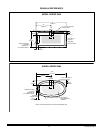
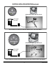
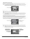
NOTE: Relocating blower motor from factory installed location, see photo 1, will require disassembly of air blower from mounting
board. Keep all hardware for reattachment at new location. Additional hardware will be required depending upon final
desired position of air blower. Follow all instructions listed below.
NOTE: Installing the blower in a remote location will reduce the system efficiency.
NOTE: Relocating a blower motor still requires a service access for the blower.
NOTE: All materials needed for the relocation must be supplied by the installer. This includes ordering a longer control panel
cable (754025-0073A), a longer flexible blower hose (753960-2030A), and up to two lighting cable extensions for combo
models (754512-0070A).
A separate circuit, which must be protected by the Ground Fault Circuit Interrupter (GFCI), is required in the remote location.
Electrical connections should be performed by a licensed electrician.
The blower motor must be located within 12 feet of rigid piping from the bath air manifold. This limitation is for the total pipe length
and applies to any direction changes and elbows. There can be no more than six changes of direction. There should be as few
direction changes as possible and the piping installation must meet all requirements of local plumbing and building codes.
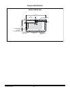
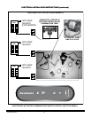
Disconnect the blower from the flexible hose as shown in photo 2. Do NOT remove the check valve manifold that is mounted to the
underside of the air bath. The manifold MUST remain mounted above the tub overflow level as shown in 2.
Replace the flexible hose shown in photo 2 with the longer flexible hose (P/N 753960-2030A) using the existing hope clamps.
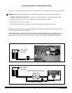
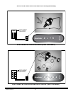
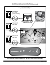
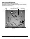
NOTE: Do NOT remove the original cable coming out of the blower. Instead, plug the longer cable (P/N 754025-0073A) into the
existing cable that is coming out of the blower as shown in photo 3. Then plug the remaining end of the longer cable into
the control panel which remains on the tub wall.
1.
2.
3.
TYPICAL VIEW
TYPICAL VIEW
Do NOT move check
valve manifold
TO CONTROL PANEL
754025-0073A CABLE
(INCLUDES ADAPTER
BOX SHOWN)
TO BLOWER
EXISTING
CABLE


