American Dryer • 12932 Farmington Road • Livonia • MI • 48150 •U.S.A. • www.americandryer.com
phone (734) 421-2400 • toll free (800) 485-7003 U.S. only • fax (734) 421-5580
© 1999-2006 American Dryer, Inc. All rights reserved. Specifications subject to change without notice. Revised August 2005
Architect’s Specifications
Warranty
10-year limited warranty includes same day factory repair
or part replacement. Sensor 3 years. See owner’s manual
for details.
The dryer shall be manufactured by American Dryer to
include a 16 gauge reinforced steel cover with a white
enamel finish or 18 gage reinforced stainless steel cover
with satin finish. Recessed units will include a 16 gauge
steel wall mounting box. Motor shall be a shaded pole,
maintenance-free, brushless type. Motor requires no
brushes, oiling or fuses. This motor shall be thermally over-
load protected, 1/10 HP, 3200 RPM. Dryer shall deliver 160
CFM at 5500 LFM. Push button dryers shall be activated
by a cam-operated mechanical timer.
Cover shall be attached with one tamper-resistant bolt and
a 3” steel latch which locks it securely to base. Tamper-
resistant air intake vents, internal shield and side mounted
heating element are for additional safety. Heating ele-
ment is protected by an automatic resetting circuit breaker.
Nozzle and push button shall be zinc die castings with a
chrome plated finish. Nozzle shall revolve 360˚ unless
specified as fixed position. UL and C-UL listed. Made in the
U.S.A.
Operating Costs
The only operating cost for the DR series hand dryer is
electricity. Based on a cost of $0.10 per KWH:
Cost per 1,000 hand dryings
DR series = $1.92
Paper Towels = $20.56
(Refer to recessed instructions for recessed mounting)
WARNING: DISCONNECT POWER BEFORE INSTALLING
1. To remove cover, remove special Allen screw using wrench
supplied. Place a hand on each side of cover and pull bottom
toward you about 1/4 inch, then push cover up toward top of
dryer, releasing cover from mounting plate latch. Lift cover off
mounting plate by pulling forward at the bottom and upward at
the same time. DO NOT FORCE COVER OFF.
2. Dryers should be placed at least 2 feet (61cm) apart and at
least 12” (30cm) from washbasin. Do not install dryers over
washbasin. Hold the backplate to the wall at the suggested
mounting height. Measure from bottom edge of backplate to the
floor.
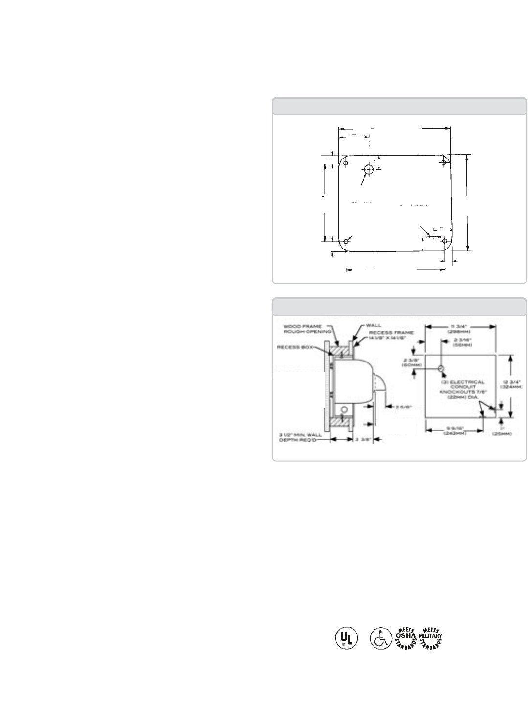
3. Mark the locations of the four mounting holes and the con-
duit entrance location on the wall. (The conduit entrance is the
proper hole diameter for 1/2 inch (13mm) conduit.)
4. Fasten the backplate to the wall where previously marked.
RECOMMENDATION:
Wood wall - No. 16 (M8) wood screws, 2 3/4”(70mm) long
Cement or brick - 1/4” (M6) stud expansion bolts, 3” (76mm)
long
Hollow wall - 1/4” (M6) toggle bolts, length depends on wall
thickness
5. Run service wire to dryer location and connect to terminal
block. IMPORTANT: All units must be supplied with a 3 wire
service. Use No. 12 wire or larger as required by local electrical
code. The ground wire must be connected to the dryer back-
plate. Unit must be installed by a qualified licensed electrician.
Do not connect any unit to a branch circuit over 20 amps.
Dryers located in shower rooms or other wet locations should be
equipped with ground fault interrupter(s).
6. Carefully replace the cover using tamper-proof bolts sup-
plied.
Installation (Surface Mount)
Mounting Heights:
Suggested mounting heights from floor to bottom of dryer:
MEN WOMEN CHILDREN HANDICAPPED
“DR-N” Hand Dryer... 42” (107cm) 40” (102cm) 30-40” (76-102cm) 34” (86cm)
“DR-NH” Hair Dryer... 72” (183cm) 68” (173cm) 46-68” (117-173cm) 52” (132cm)
Dimensions:
WIDTH HEIGHT DEPTH NET WEIGHT
Surface Mounted 11” 9-1/4” 6-5/8” 16 lbs. (7kg)
Recessed Mounted 14-1/8” 14-1/8” 3-3/8” 23 lbs. (10kg)
DR Series Surface Mounted
9 1/16
(230 mm)
9 1/2
(241 mm)
5/8
(17 mm)
10 13/16
(274 mm)
7 7/16
(189 mm)
1 5/16 (33 mm)
5/8 (17 mm)
7/8 (22mm) DIA. IN-WALL
CONDUIT ENTRANCE
1 (25 mm)
(4) MTG HOLES
5/16 DIA. (8 mm)
2 3/4
(70 mm)
1 1/4
(32 mm)
5/8
7/8 (22mm) DIA. SURFACE
CONDUIT ENTRANCE
DR Series Recess Mounted
ROUGH
OPENING
11 3/4” W (30cm)
X
12 3/4” H 932cm)
US
C


