25
This is an important feature since with most meters the alarm
terminals close only when an abnormal situation arises, how-
ever, due to line interruption, no alarm
is sounded, causing extensive damage.
On the other hand, software is em-
ployed to set off the alarm in abnormal
circumstances, for example, if the dos-
ing terminals are closed for too long a
period. In both cases, the red LED’s will
also provide a visual warning signal.
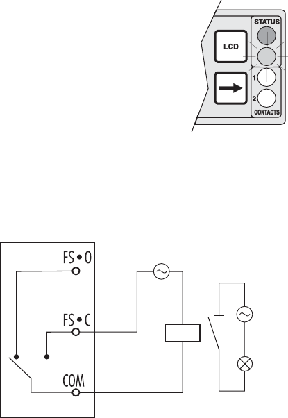
The Fail Safe mode is accomplished by connecting the exter-
nal alarm circuit between the FS•C (Normally Open) and
the COM terminals. This way, an alarm will warn the user
when EC exceeds the alarm thresholds, during power down
and in the case of a broken wire between the process meter
and the external alarm circuit.
Note In order to have the Fail Safe feature activated, an external
power supply has to be connected to the alarm device.
CONTROL THROUGH ANALOG OUTPUT
Models HI 700, HI 705 and HI 710 have a proportional
analog signal (selectable among 0-1mA, 0-20mA, 4-20mA,
0-5VDC, 1-5VDC and 0-10VDC) at the analog output ter-
minals. With this output, the actual output level amplitude is
varied, rather than the proportion of ON and OFF times
(duty cycle control). A device with analog input (e.g. a pump
with a 4-20 mA input) can be connected to these terminals.


