29
The user should select the appropriate range to calibrate (setup
code 03). Calibration must be performed for each range used.
The temperature probe should also be connected to the pro-
cess meter. The meters are equipped with a stability indicator.
The user is also guided with indications on the display during
the calibration procedure.
Initial Preparation
Pour a small quantity of the calibration solution (e.g. 1413 µS)
into a beaker. If possible, use a plastic beaker to minimize
any EMC interference.
For accurate calibration use two beakers containing the same
solution, the first one for rinsing the probe, the second one
for calibration. By doing this, contamination between the so-
lutions is minimized.
To obtain accurate readings, use the calibration solution in
the selected range and closer to the values to be measured.
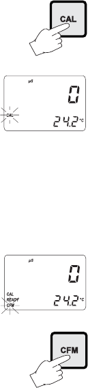
Offset Calibration
• To perform the EC or TDS calibra-
tion enter the calibration mode, by
pressing CAL and entering the pass-
word.
• After the correct password is en-
tered, the control actions stop and
the primary LCD will display the first
EC or TDS calibration value, with
the "CAL" indicator blinking. The sec-
ondary LCD displays the temperature.
Note If the wrong password is entered the system reverts back to
normal operation, displaying EC or TDS values.
• 0 is the default value for the 1
st
calibration point. Dry the
conductivity probe and leave it in air.
• Only when the reading is stable the
"CAL" indicator will stop flashing (af-
ter about 30 seconds) and the
"READY" and "CFM" indicators will
start blinking.
• Press CFM to confirm the calibration
point; the primary LCD will display
the second expected buffer value.


