


TorqueMaster
™
End Bracket Extension
Installation Instruction Insert
Components:
(1) pair End Bracket Extension
(1) TorqueMaster
™
Center Bracket Extension
(1) TorqueMaster
™
Adjustable Center Bracket
(4) 1/4” - 14 x 5/8” Self Tapping Screws
(2) 3/8” - 16 x 3/4” Truss Bolt
(2) 3/8” - 16 Hex Nut
(2) 1/4” - 20 x 9/16 Track Bolts
(2) 1/4” - 20 Hex Head Nuts
Use this insert in conjunction with the installation manual provided with the door. Follow the corresponding steps in this insert with the steps in the
installation manual.
255081
REV1 02/19/2010
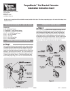
Step 1
Prior to securing the vertical track assemblies to the jamb as detailed
in the product specific installation instruction manual, first secure the
end bracket extensions to the 12” radius TorqueMaster
™
flagangles.
Locate the left and right end bracket extensions with the left and right
flagangles. Align and insert the Twistlock
™
tab in the end bracket ex-
tension with the butterfly hole in the appropriate flagangle and rotate
1/4 turn to lock into place (Figure 1). Secure the end bracket exten-
sion to the flag angle using (1) 3/8 -16 x 3/4” truss bolt and hex nut.
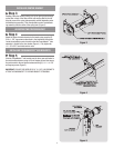
PREPARING THE CENTER BRACKET
Step 2
Before installing the adjustable center bracket, the bushing must be
removed from the standard center bracket. First twist strait arm on
both the standard and adjustable center brackets so that the bush-
ing may pass through. After pulling the bushing from the standard
center bracket, place it into the adjustable center bracket and twist
the straight arm back to the original position. Align the center bracket
extension with the adjustable center bracket and loosely fasten with
two (2) 1/4” - 20 x 9/16” track bolts and hex nuts (Figure 2).
Figure 2
Figure 1
©Copyright 2010 Wayne-Dalton, a Division of Overhead Door Corporation
Wayne-Dalton, a Division of Overhead
Door Corporation
P.O. Box 67
Mt. Hope, OH 44660
www.Wayne-Dalton.com
ATTACHING THE END BRACKET EXTENSION
END BRACKET EXTENSION KIT : PART NO. 255084