


may be stored in a "configuration
file" on the PC for future use.
After configuration, and at periodic
intervals, the calibration may be veri-
fied by simulating and varying the
input signal over the defined range
and comparing the output signal to
the ideal. If calibration is necessary,
the PC software is used to adjust the
transmitter's digital references. Be-
cause of the self-calibrating technol-
ogy utilized in the TX787, the cali-
bration verification interval may be
significantly longer than for earlier
technology transmitters.
The Calibration and Configuration
Software, Isolated RS232/TX787
Communications Adapter and User's
Guide are included in the model
TX780-SOFT.
by spikes and surges on field wiring
entering the computer via its unpro-
tected serial port.
The TX787 utilize state of the art
microprocessor technology and
yields higher accuracy and long-
term stability with lower power con-
sumption than prior generation trans-
mitters. The device automatically
performs frequent self-testing and
auto-calibration while in service, re-
sulting in very stable long-term per-
formance - stability greater than
0.1% of span over 12 months.
To maximize traceability, each unit
may be assigned a tagID, a job or a
project number, the purchase order
and date on which it was procured,
and a message in addition to its
serial number. This data, along with
the selected input type and range,
last calibration date, and serial num-
ber are stored in the transmitter.
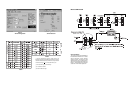
OPERATION
Every TX788 is factory calibrated
and may be simply configured to
perform the desired function using
the Device Configuration screen (fig-
ure 1) and the Sensor Selection
screen (figure 2) shown. Just fasten
the DB-9 connector to the computer's
serial port and the keyed 5-pin con-
nector to the port under the access
cover on the top or the transmitter.
There is no need to provide an ex-
ternal power supply and load to the
TX787's output to configure the
transmitter.
Units previously placed in service
may have their configuration " up-
loaded" to the PC. Their operating
parameters may be reviewed and if
necessary revised and downloaded
again. All configuration parameters
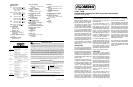
APPLICATION
Model TX787 and TX788 is an ex-
tremely versatile two-wire transmit-
ter that may be used in any applica-
tion requiring an isolated 4-20mA
current loop proportional to a ther-
mocouple, RTD, millivolt, milliamp,
voltage, resistance or potentiometer
input. Typical applications include
providing accurate, stable signals to
distributed control systems (DCS),
supervisory control and data acqui-
sition systems (SCADA), environ-
mental monitoring and control sys-
tems (EMCS), data acquisition and
control systems (DACS) and cus-
tody transfer / pipeline systems. The
output of the TX787 and TX788 may
also be used by an analog or digital
display device.
DESCRIPTION
The TX787 is a programmable two-
wire transmitter that is configured to
provide an isolated 4-20mA signal in
proportion to the desired range of its
input signal. The TX787 accepts ther-
mocouple, 2-,3-, or 4 wire RTD, po-
tentiometer, and millivolt inputs. The
TX788 accepts millivolt, voltage, and
milliamp inputs.
Configuration is performed by con-
necting the transmitter to a standard
PC serial port (9-pin RS232C) using
an isolated interface adapter and
running a user-friendly, Windows-
based program. Unique
PC-Only
technology in the TX787 allows all
configuration information to be de-
fined and modified with only a PC,
the interface adapter, and the trans-
mitter. No loop supply, input simula-
tion, or meter on the output is re-
quired! The fully isolated adapter
reduces the risk of expensive dam-
age to the PC which can be caused
TX787, TX788
Programmable, Isolating Two-Wire Temperature Transmitters
Instruction Sheet M-2919
1
SPECIFICATIONS
Minimum Span
t/c: 20
0
C if zero offset < 650
0
C
50
0
C if zero offset > 650
0
C
125
0
C if zero offset > 1250
0
C
(type C only)
RTD: 12
0
C if zero offset < 75
0
C
20
0
C if zero offset < 275
0
C
50
0
C if zero offset > 275
0
C
mV: 1mV if zero offset < 25mV
5mV if zero offset < 150mV
10mV if zero offset > 150mV
mA: 1mA if zero offset < 15mA
3mA if zero offset > 15mA
Volts: 0.3V if zero offset < 5V
0.5V if zero offset > 5V
Input Impedence
Volts: 200kΩ
Millivolts: 10mΩ
Milliamps: 5Ω
t/c Burnout Function
Programmable: upscale or
downscale
t/c Burnout Detection Current
<0.2µA
RTD Excitation Current
0.3mA (nominal)
Filter Band
Programmable from 0 to 120%
Damping
Programmable from 0.0 to 32.0
seconds
Common Mode Rejection
120dB
Operating Temperature Range
-20 to 70
o
C
Dimensions mm(inches)
H 55.3 (2.10) X W 77.7 (3.06)
X D 61.0 (2.40)
Weight
0.56lbs
Warranty
3 years
Long Term Stability
Better than 0.1% of span in 12
months
Temperature Stability
<0.01% of span per
0
C
Isolation
1000VDC input to output
Minimum Output Current
3.85mA
Maximum Output Current
22.5mA
Loop Voltage Drop
< 9VDC at 20mA
Supply Voltage Range
9 - 36 VDC
Maximum Effect of Change in
Supply Voltage
<0.002% of span per Volt
Effect of Ambient Temperature
Change on Cold Junction
Compensation
0.02
0
C/
0
C
CJC Accuracy
0.5
0
C
Update Time
>3 Conversions per second
Turn On Time
< 4 Seconds
Servicing North America:
Fax: (95) 203-359-7807
e-mail: espanol@omega.com
Fax: (514) 856-6886
Fax: (203) 359-7700
Servicing Europe:
Fax: (31) 20 6434643
Fax: 49 (07056) 8540
Postbus 8034, 1180 LA Amstelveen, The Netherlands
Tel: (31) 20 6418405
Toll Free in Benelux: 06 0993344
e-mail: nl@omega.com
Ostravska 767, 733 01 Karvina
Tel: 42 (69) 6311899
e-mail: czech@omega.com
9, rue Denis Papin, 78190 Trappes
Tel:33 0130-621-400
Toll Free in France: 05-4-06342
e-mail: france@omega.com
Daimlerstrasse 26, D-75392 Deckenpfronn, Germany
Tel:49 (07056) 3017
Toll Free in Germany: 0130 11 21 66
e-mail: germany@omega.com
25 Swannington Road,
Broughton Astely, Leicestershire,
LE9 6TU, England
Tel: 44 (1455) 285520
Fax: 44 (1455) 283912
Fax: 33 0130-699-120
Fax: 42 (69) 6311114
P.O. Box 7, Omega Drive
Irlam, Manchester,
M44 5EX, England
Tel: 44 (161) 777-6611
Fax: 44 (161) 777-6622
Toll Free in England: 0800-488-488
e-mail: uk@omega.com
976 Bergar
Laval (Quebec) H7L 5A1
Telephone: (514) 856-6928
e-mail: canada@omega.com
For immediate technical sevice or application assistance:
Sales Service: 1-800-826-6342 / 1-800-TC-OMEGA
SM
Customer Service: 1-800-622-2378 / 1-800-622-BEST
SM
Engineering Service: 1-800-872-9436 / 1-800-USA-WHEN
SM
TELEX: 996404 EASYLINK: 62968934 CABLE: OMEGA
Tel: (95) 800-TC-OMEGA
SM
En Espanol: (203) 359-1660 ext. 2203
One Omega Drive, Box 4047
Stamford, CT 06907-0047
Telephone: (203) 359-1660
e-mail:info@omega.com
USA:
ISO 9001 Certified
Canada:
USA and Canada:
Mexico and
Latin America:
Benelux:
Czech Republic:
France:
Germany/Austria:
United Kingdom:
ISO 9002 Certified
Internet e-mail
info@omega.com
OMEGAnet
SM
On-Line Service
http://www.omega.com
WARRANTY/DISCLAIMER
RETURN REQUEST/ INQUIRIES
Direct all warranty and repair requests/inquiries to the OMEGA Customer Service Department. BEFORE RETURNING ANY PRODUCT(S) TO OMEGA,
PURCHASER MUST OBTAIN AN AUTHORIZED RETURN (AR) NUMBER FROM OMEGA'S CUSTOMER SERVICE DEPARTMENT (IN ORDER
TO AVOID PROCESSING DELAYS). The assigned AR number should then be marked on the outside of the return package and on any correspondence.
The purchaser is responsible for shipping charges, freight, insurance and proper packaging to prevent breakage in transit.
FOR WARRANTY RETURNS, please have the following information
available BEFORE contacting OMEGA:
1. P.O. number under which the product was PURCHASED,
2. Model and serial number of the product under warranty, and
3. Repair instructions and/or specific problems relative to the product
OMEGA ENGINEERING, INC. warrants this unit to be free of manufacturing defects for the life of the product.
If the unit should malfunction, it must be returned to the factory for evaluation. OMEGA's Customer Service Department will issue an
Authorized Return (AR) number immediately upon phone or written request. Upon examination by OMEGA, if the unit is found to be defective
it will be repaired or replaced at no charge. OMEGA's WARRANTY does not apply to defects resulting from any action of the purchaser,
including but not limited to mishandling, improper interfacing, operation outside of design limits, improper repair, or unauthorized modifica-
tion. This WARRANTY is VOID if the unit shows evidence of having been tampered with or shows evidence of being damaged as a result
of excessive corrosion; or current, heat, moisture or vibration; improper specification; misapplication; misuse or other operating conditions
outside of OMEGA's control. Components which wear are not warranted, including but not limited to contact points, fuses, and triacs.
OMEGA is pleased to offer suggestions on the use of its various products. However, OMEGA neither assumes responsibility for
any omissions or errors nor assumes liability for any damages that result from the use of its products in accordance with
information provided by OMEGA, either verbal or written. OMEGA warrants only that the parts manufactured by it will be as
specified and free of defects. OMEGA MAKES NO OTHER WARRANTIES OR REPRESENTATIONS OF ANY KIND WHATSOEVER,
EXPRESSED OR IMPLIED, EXCEPT THAT OF TITLE, AND ALL IMPLIED WARRANTIES INCLUDING ANY WARRANTY OF MER-
CHANTABILITY AND FITNESS FOR A PARTICULAR PURPOSE ARE HEREBY DISCLAIMED. LIMITATION OF LIABILITY: The rem-
edies of purchaser set forth herein are exclusive and the total liability of OMEGA with respect to this order, whether based on
contract, warranty, negligence, indemnification, strict liability or otherwise, shall not exceed the purchase price of the compo-
nent upon which liability is based. In no event shall OMEGA be liable for consequential, incidental or special damages.
CONDITIONS: Equipment sold by OMEGA is not intended to be used, nor shall it be used: (1) as a "Basic Component" under 10 CFR 21
(NRC), used in or with any nuclear installation or activity; or (2) in medical applications or used on humans. Should any Product(s) be used
in or with any nuclear installation or activity, medical application, used on humans, or misused in any way, OMEGA assumes no responsi-
bility as set forth in our basic WARRANTY/DISCLAIMER language, and additionally, purchaser will indemnify OMEGA and hold OMEGA
harmless from any liability or damage whatsoever arising out of the use of the Product(s) in such a manner.
FOR NON-WARRANTY REPAIRS, consult OMEGA for current
repair charges. Have the following information available BEFORE
contacting OMEGA:
1. P.O. number to cover the COST of the repair,
2. Model and serial number of product, and
3. Repair instructions and/or specific problems relative to the
product.
OMEGA's policy is to make running changes, not model changes, whenever an improvement is possible. This affords our customers the latest in technology
and engineering.
OMEGA is a registered trademark of OMEGA ENGINEERING, INC.
ã Copyright 1996 OMEGA ENGINEERING, INC. All rights reserved. This documentation may not be copied, photocopied, reproduced, translated, or reduced
to any electronic medium or machine-readable form, in whole or in part, without prior written consent of OMEGA ENGINEERING, INC.
It is the policy of OMEGA to comply with all worldwide safety and EMC/EMI regulations that apply. OMEGA is constantly pursuing certification of its products to
the European New Approach Directives. OMEGA will add the CE mark to every appropriate device upon certification.
The information contained in this document is believed to be correct but OMEGA Engineering, Inc. accepts no liability for any errors it contains, and reserves the
right to alter specifications without notice.
WARNING: These product are not designed for use in, and should not be used for, patient connected applications.
721-0709-00A 8/98