CENTRAL CLEANING SYSTEM
Indicating Inlets
MODELS: CI370 Series
USE ONLY WITH CV653, CV750 & CV850 POWER UNITS
Mounting Bracket
MODEL: 361
INSTALLATION
1. Once the locations for wall inlet locations have been
determined, mount all inlet brackets.
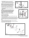
2. To locate bracket on wall stud, measure approximately 18" up
from finished floor level. (Height location may vary according to
individual preference.)
3. Refer to Figure 1. Nail bracket to side of stud so that front
edge of bracket is flush to front of stud. (The bracket may also
be nailed to the front edge of the stud. For front stud mounting,
use locating tabs on bracket for proper alignment.)
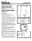
4. Refer to Figure 2. Remove cardboard from plaster guard
frame. Using four (4) provided screws, attach the appropriate
flanged fitting and inlet seal to back of inlet.
5. Replace cardboard into plaster guard frame.
6. Plumb tubing to inlet. Run 2-conductor (376 or 376UL)
low voltage cable between inlet and power unit.
CAUTION: When tubing is run through the wall stud, sole
plate, headers – or anywhere that building materials will be
attached – place a nail plate (Model 378) over that area (on
both sides if necessary) to prevent nails from piercing tubing.
WALL INLET INSTALLATION
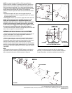
1. Once the walls have been finished, install the wall inlets.
2. Remove the cardboard plaster guard.
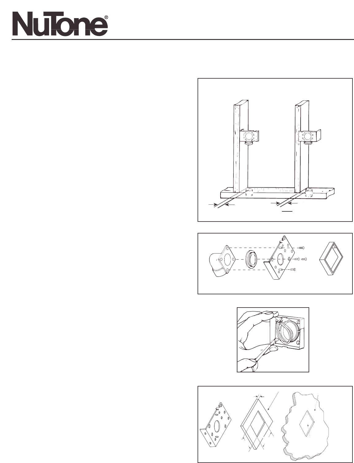
3. Refer to Figure 3. For some dry wall or panel construction,
the plaster frame will extend beyond the finished wall. In this
case, remove plaster frame from mounting bracket by
removing mounting screws.
NOTE: When using the Model 361 inlet bracket on walls
thinner than
1
⁄2", use a
1
⁄4" spacer (not furnished) between
the wall and the inlet bracket. See Figure 3A.
Spacer may be made from plywood, Masonite™, etc. Contact
cement may be used to hold spacer in place during assembly.
Configuration of spacer may vary depending upon installation.
INSTALLATION INSTRUCTIONS
READ & SAVE THESE INSTRUCTIONS!