


Part No. 1090132 Rev F 19 Invacare Scooters
PROCEDURE 3OPERATION
WARNING
After ANY adjustments, repair or service and BEFORE use, make sure
that all attaching hardware is tightened securely. Otherwise, injury or
damage may result.
CONTROL PANEL FEATURES
ALL SCOOTER MODELS
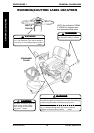
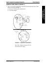
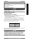
With Delta or Standard Tillers (FIGURE 1).
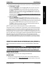
1. Speed Control Knob - Located on the top face of the control panel. The number
one (1) represents the slowest speed and the number ten (10)
represents the fastest speed (DETAIL "A").
2. Battery Charge-Indicator - The charger indicator is located on the top face of
the control panel and has an "E" indicating EMPTY and an "F" indicating FULL.
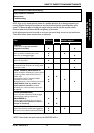
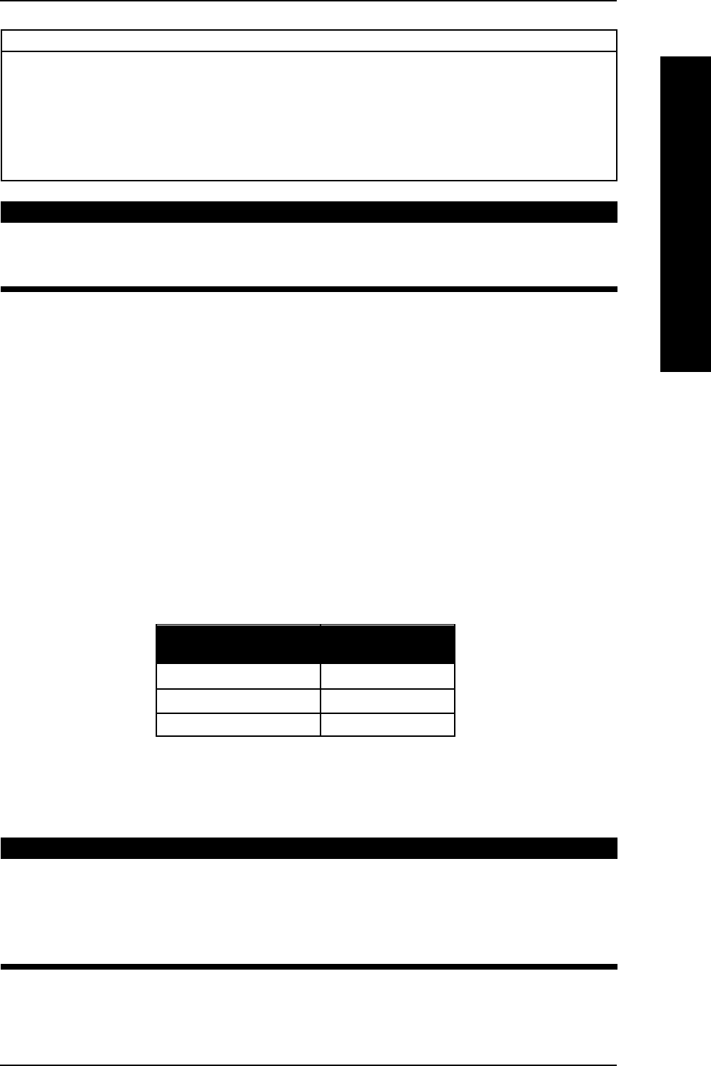
NOTE: The battery charge indicator is composed of eight (8) bars which, when the power is
turned on, will illuminate showing the charge level of the batteries. The more number of bars
illuminated the more charge the batteries have. See chart below.
NOTE: The number of bars illuminated may decrease when driving over uneven surfaces even
with batteries fully charged. True reading is with key inserted and
indicator illuminated with powered scooter stationary.
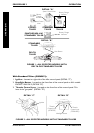
WARNING
When negotiating ramps, if the throttle control lever is released while in
FORWARD motion the powered scooter will "ROLLBACK" approxi-
mately one (1) foot before brake engages. If the throttle control lever is
released while in REVERSE motion the powered scooter will "ROLL-
BACK" approximately three (3) feet before brake engages.
3. Horn Button - Located on front face of control panel toward the left. (DETAIL "B").
OPERATION
This Procedure Includes the Following:
Control Panel Features
Operation of the Scooter
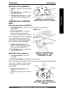
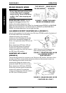
Using the Hand Brake Lever/Brake Arm
Brake Release Lever
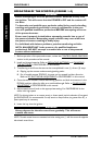
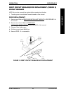
Reset Circuit Breaker/Fuse Replacement
NUMBER OF CHARGE
BARS ILLUMINATED OF BATTERIES
8 fully charged
4 partially charged
0 discharged